Possible QSD/ISD Switches/ ADC Idea/Misc


QSD/ISD Switches:

Here is a link the PDF data sheets of analog switches that can be investigated for use in QSD/ISD circuits:

http://www.philcovington.com/HPSDR/QSD_SWITCH/

Interesting ADC:

Here is a link to an interesting ADC by Analog Devices:

http://www.analog.com/UploadedFiles/Data_Sheets/AD7760.pdf

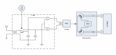
It is a 24 bit, 2.5 MSPS ADC. Here is the circuit idea:

http://www.philcovington.com/HPSDR/TEMP_STUFF/AD7760QSD.pdf

It uses 1/2 of a QSD (not quadrature sampled) to mix the frequency band of interest down to zero Hz with a bandwidth of something like 250 kHz. The IF would be offset to something like 125 kHz. The ADC samples the 1/2QSD output and results in a real data stream. A FPGA or CPLD mixes the real data stream with a complex NCO to generate a quadrature data stream which is sent over USB to the PC where the remaining processing is done. The advantage is a 1 X LO and no I/Q balance problems. One disadvantage is that your sampling rate should be 4 times the desired bandwidth. For narrow band applications this should be no problem because the AD7760 will sample up to 2.5MSPS. A 500 MSPS rate into the PC should allow a bandwidth of almost +/- 125 kHz from the LO frequency.

Nice SDR Enclosure?

Ken N9VV sent me a link to a cool PC case:

http://www.origenae.com/product_x15e.htm

Comments

Anonymous said…
It is my feeling that it won't work... converting to baseband not in quadrature will irremediably mix together the upper and the lower sidebands, and no further processing will be able to separate them again...
Phil Covington said…
I think you are misundertanding the diagram. I am mixing to an intermediate IF within the 1.25 MHz passband of the AD7760, not to zero Hz. It is no different than mixing a 100 MHz signal down to 5 MHz and sampling with a 20 MSPS ADC. As long as the signal bandwidth you are interested in is less than half of the sampling rate, it will be OK.
Anonymous said…
Ok,then you are right. But maybe you should modify the opening sentence of your description, which says :
---------------
It uses 1/2 of a QSD (not quadrature sampled) to mix the frequency band of interest down to zero Hz with a bandwidth of something like 250 kHz.
---------------

From it one could understand that you are really converting to zero Hz, not at an intermediate IF.
Phil Covington said…
It actually does mix the band of interest down to 0Hz, but with a bandwidth of say 250 kHz, the IF would be offset at say 125 kHz in a similar way that the SDR-1000 uses an IF of around 11 kHz. Still I can see how the statement could be confusing.
Anonymous said…
AD7760 would be an excellent choice. To improve its dynamic range further you should use it only in a suboctave frequency range, to have lower harmonics kept out which are responsible for the strongest spurii. I am working on such a project.

Pieter-Tjerk PA3FWM has used the 7760 in an experiment with a I/Q radio, see http://wwwhome.cs.utwente.nl/~ptdeboer/ham/sdr/#jun2006

Popular posts from this blog

History of HPSDR Mercury and Quick Silver

History of HPSDR Mercury and Quick Silver Philip Covington, N8VB Early HPSDR and XYLO In 2005 I started a High Performance SDR (HPSDR) project which was to consist of a motherboard carrying a FPGA/USB 2.0 interface and power supply with the provision for plug in modules through 40 pin headers. I had planned a narrow band high dynamic range module based on a QSD/DDS/PCM4202 audio ADC and a wide bandwidth module based on a high speed 16 bit ADC: http://www.philcovington.com/SDR/PICS/HPSDR_FPGA_USB_Board_top1_800600.jpg http://www.philcovington.com/SDR/PICS/HPSDR_FPGA_USB_Board_top4.jpg I soon selected the LTC2208 ADC from Linear Technology. A representative from Linear Technology came across my blog ( http://pcovington.blogspot.com/ ) and offered evaluation boards and samples to support the project. At about the same time my HPSDR project came about, Phil Harman, VK6APH and Bill Tracey, KD5TFD were interested developing a sound card replacement to be used with the SD...

2323 Wilt

RFFE1 Why you may (or may not) need it

RFFE stands for "Radio Frequency Front End" and the "1" stands for the first version (0-62.5 MHz coverage). When I was designing the QS1R board, I had to decide whether to include bandpass filtering and RF amplification on the board. In fact the initial prototypes "RevA" included RF amplification on the QS1R board. Unlike another DDC based direct sampling receiver "Perseus", QS1R was designed to be more than a SW receiver. In addition to a SW receiver, QS1R was meant to facilitate experimentation in the RF spectrum up to at least 300 MHz. I finally settled on a 55 MHz low pass filter (which can be bypassed) and no active components in front of the ADC on QS1R. Any active devices, bandpass filters, or attenuation would be added by a separate board such as the RFFE1. The antenna that I use for my QS1R is a center fed, non-resonant dipole at 50 feet. The total wire length is about 240 feet with only about 100 feet of that running horizontally...